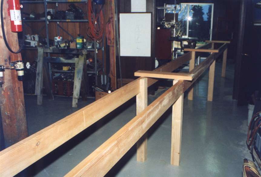
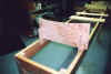
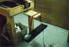
| After making the big decision to build an airplane the next step waiting, is hard.
While waiting for the delivery of the kit I occupied my time with reading the manuals and
building the jigs, setting up the work area as I thought would be necessary. The start of
the wing jig frame is shown here. |
 |
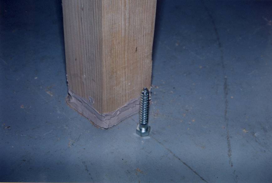
| I put a lag screw into the bottom of each leg of the wing frame legs to allow the jig
to be leveled. After leveling each of the legs of the wing jig are bonded to the
floor using body putty. |
 |
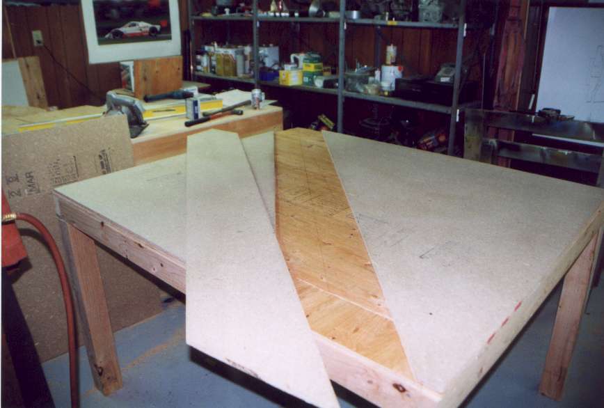
| Using patterns from the manual, frames were cut to contour the lower surface of the
wing. Some of these are placed in position but can slide up and down when the wing is
placed in the jig. This allow for the wing to be leveled. |
 |
| When the wing is place into the jig, each of the forms is adjusted up and down as well
as level until the wing is fully supported level and free from twist. |
 |
| Multiple points on the wing were used to ensure that the wing was level as well as
untwisted. |
 |
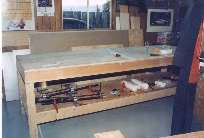
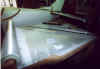
| A flat table was made for the construction of the stabilizer and elevators. |
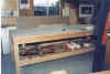 |
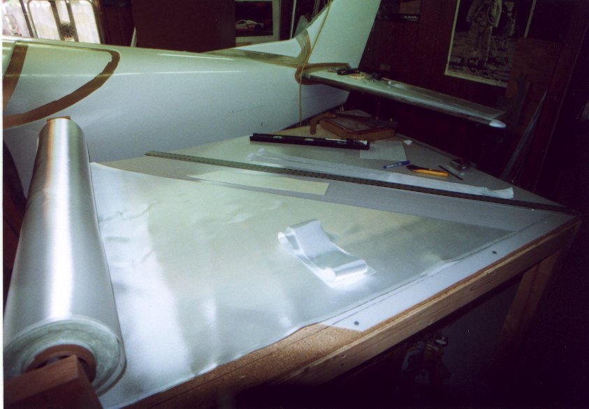
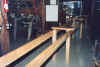
| A large cutting table was made. As most of the cutting of the Fiberglas is on a 45
degree angle or bias I made a section that was replaceable. So after years of cutting in
the same spot a new piece can be put in. |
 |
| After the jigs were made, the thought crossed my mind that I still don't have the kit
and the work area is full, is this going to be possible? |
 |
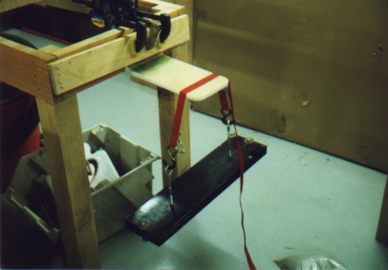
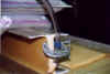
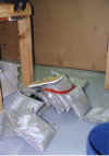
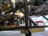
| OK, what in the would is this? Well after cutting out the nose landing gear opening in
the fuselage I tested the removed piece to see just how strong it was. Here it is with 60
pounds applied at a 10 inch moment. The test sample is 6.5 inches wide. |
 |
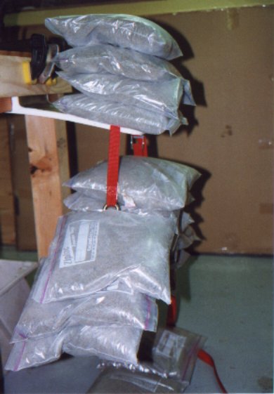
| This is just before failure. Applied is 210 pounds, for a bending load of 2100 in/lbs.
This is about 320 in/lbs. per inch of seam. |
 |
| Here it is after the failure. Look mom no toes, just a mess. |
 |
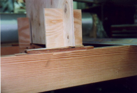
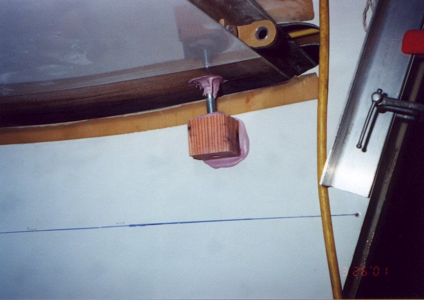
| This little fixture made setting the stabilizer into position easier than the
technique recommend by the manual . By threading the bolt in or out of a nut within the
wood block the stab can be correctly positioned. This is still a time consuming task, but
this fixture made it much easier. |
 |
| I tried all kinds of cutting table surfaces. Particle board, linoleum, Formica but the
best by far is polyethylene or HDPE. About $30 at the local plastic dealer for a 1/8 thick
4' by 8' sheet. Don't mess around, this is the stuff to get! And it lasts, cut after cut. |
 |
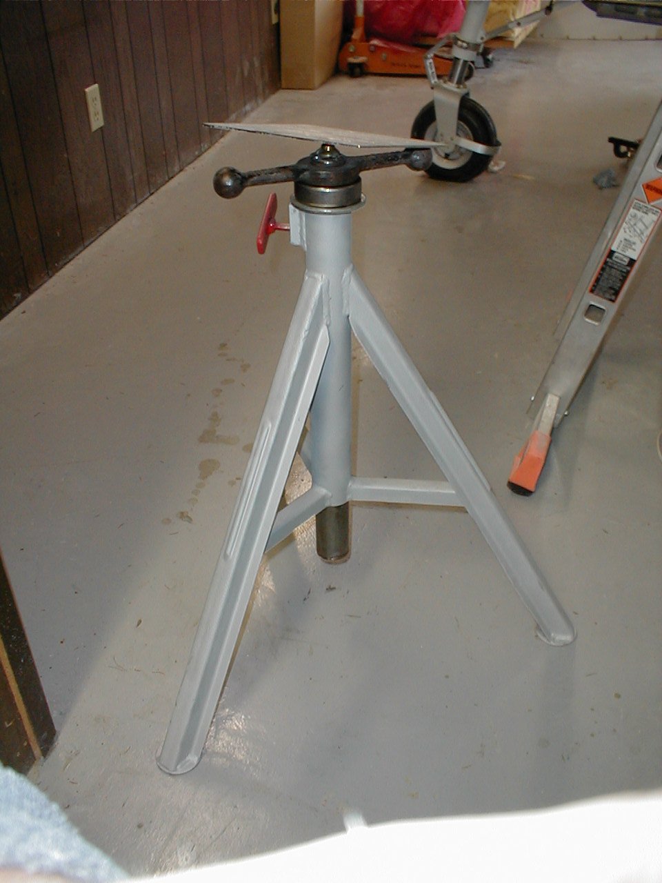
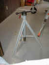
| I made two wing jacks from old pipe stands. I add a trust bearing to
allow the airplane to be lifted with very little effort. |
 |
| Why are most Glasairs painted white? What if I don�t what a white
airplane, what is going to happen? Ok,
there are some Glasair that are not painted white. But there is a very
good reason that most are painted white, heat is the enemy of vinyl ester
resin. High temperatures will soften and damage the airframe. I set out to
find what the temperature difference of varies colors would be. I located
a piece of old wing skin, no I didn�t screw up that bad that I had a
spare wing lying around. The cutouts of the seat pan area seamed like an
excellent source of simulated wing skin. I cut 6 pieces 4.5 inches square
from the old seat pan cutouts and painted them different colors. I choose
a range of colors to include standard white as well as yellow, red, blue,
green, and black. |
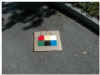 |
| After painting and preparing each of the sample wing skins a
thermocouple was attached to the center on the back on each of the test
coupons. This would measure the temperature of the shin as seen inside the
structure. All six coupons where then mounted on a piece of cardboard this
would act as an insulator from the ground. As all the sample where mounted
to the cardboard all would be exposed to the sunlight at the same time
and in the same manor during the test. The complete test setup was then
exposed to direct sunlight. The shadow shown next to the sample panels in
the photo, moves away from the panel as the day passes.
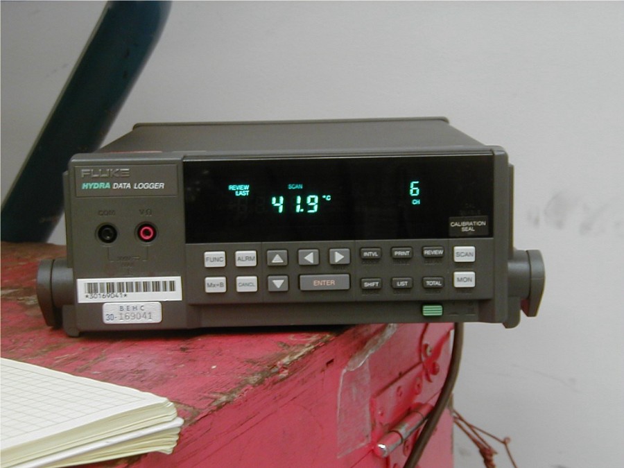
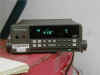
Data was collected at 15-minute intervals using a Fluke data logger
with an accuracy of +/1 degree. In addition to the six-temperature
measurement the ambient temperature was also record. |
 |
|
Observations:
 | As
quickly as I was able to set the panel on the ground and start the
data acquisition system there was a notable change in the temperature. |
| White
is the coolest color and Black is the hottest |
| The
surface temperature can be much hottest than the ambient air
temperature. It is more a function of infrared radiation than air
temperature. |
| Yellow
would be a great color for the airplane. |
|

|
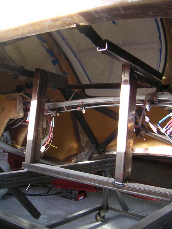
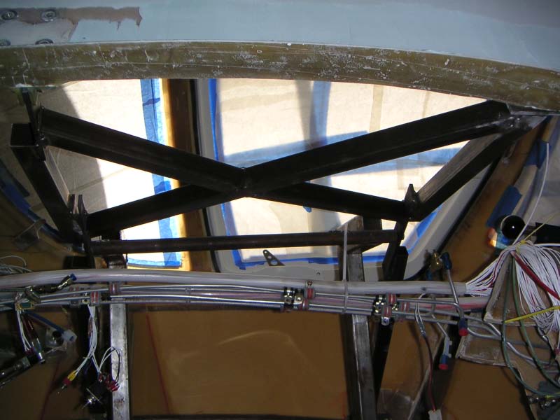
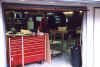
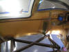
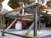
| I build a jig to hold the fuselage during painting
out of square steel tube. Its not pretty, but it works. The fuselage can
rotate about it's centerline about +/- 20 degrees. |
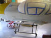 |
| These photos are not very good at showing how this is
put together. I will try and take some better ones when the fuselage is not
attached. |
 |
| |
 |
| |
|
| |
 |
| |
|
| |
 |
| |
 |