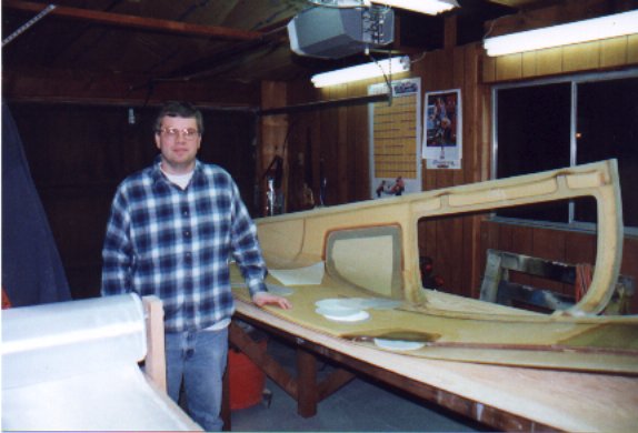
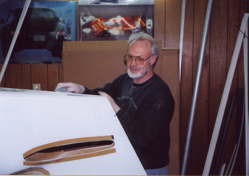
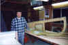
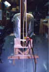
| Yours truly starting the fuselage construction.
(Jan 99) |
 |
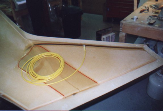
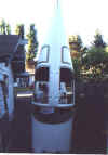
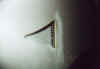
| Com antenna installed in the vertical stabilizer. The
antenna is the same copper foil design that was used in the horizontal stabilize for the
nav. |
 |
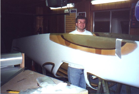
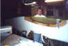
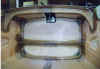
| Inverted flight. Laminating the seam between the two
fuselage halves. At this point the combined fuselage is too large to be stored in any part
of the house but the garage. |
 |
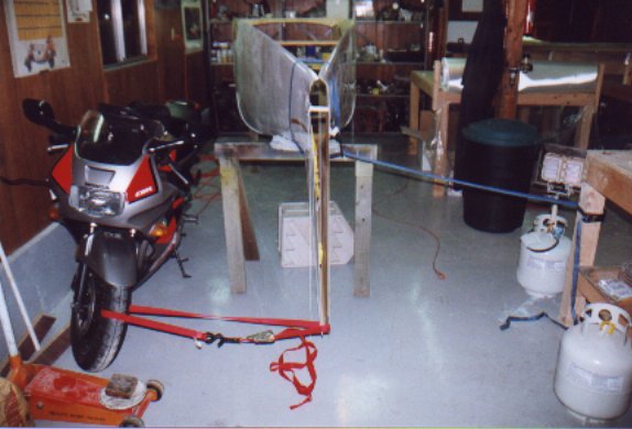
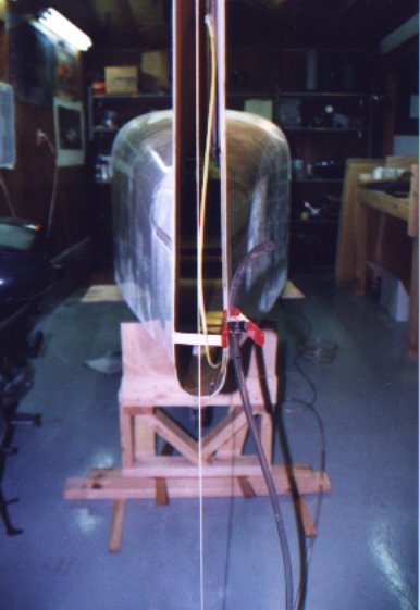
| Holding the vertical stab straight during the laminating of
the two halves. Just be sure to untie the bike before use. |
 |
| A water level and pump bob is used to ensure that the
fuselage is level and true before completing the seams between the fuselage halves and
belly pan. |
 |
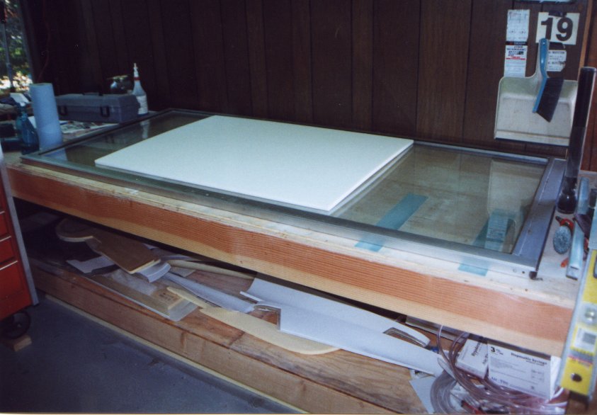
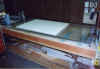
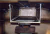
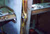
| Construction of the firewall starts. The firewall needs to
be flat, so what better than build it on a piece of glass. Using a old double
pane sliding
glass door, I built-up the foam core of the firewall into a stiff flat laminate. Now if
only I could find were that draft was coming from. |
 |
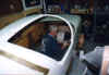
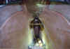
| We took the fuselage outside and stood it on its nose to
complete the lay-ups on the inside of the firewall. |
 |
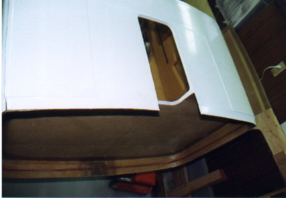
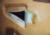
| The cutout of the nose landing gear can be seen. Cutting
holes is hard, I hope its in the right place. |
 |
| Looking at the inside of the firewall, the fuselage is
upside down. The cutout for the nose gear is at the top. The reinforcement rib along
the firewall can be seen. |
 |
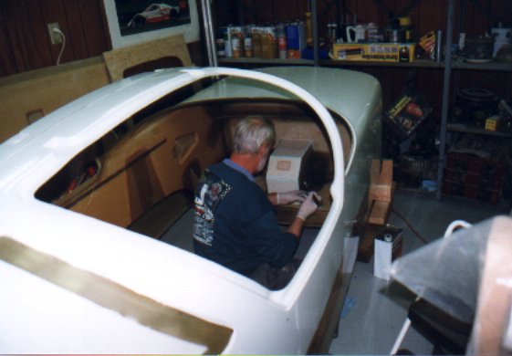
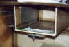
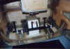
| Dad working on the firewall and nose landing gear wheel
well. |
 |
| Dad's handy work. Some more gussets need to be installed for
the engine mount, but almost complete. |
 |
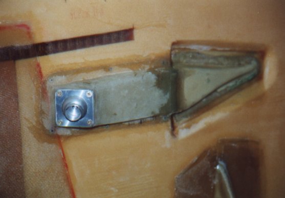
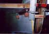
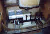
| Fresh air vents installed. Air will enter a NACA duct and is
fed to this cool ball valve. In the big airplane world this valves that are normally over
the seats of the passenger are called "gaspers". |
 |
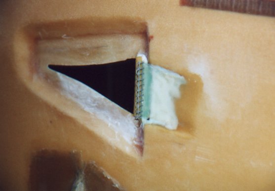
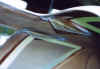
| The lip of the NACA duct is put in place. |
 |
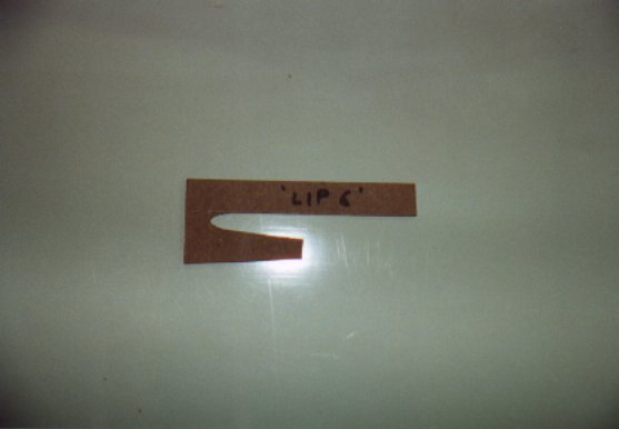
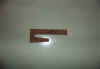
| Template for lip #6. Dad did the research to find the
correct lip shape. This will help reduce the drag from the NACA duct. |
 |
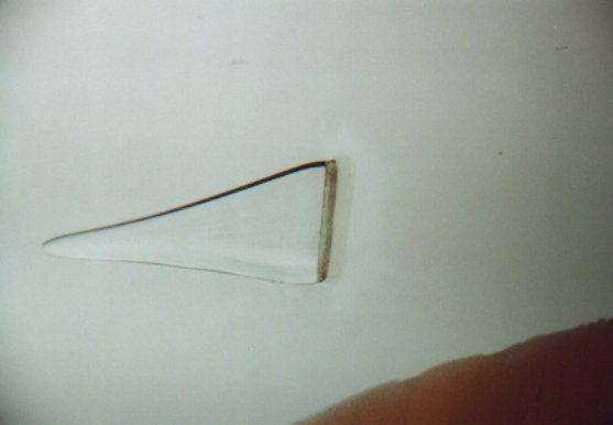
| The outside view of the fresh air inlet. |
 |
| A screen was placed in the inlet to help stop the big
bugs from coming into the cabin in one piece. |
 |
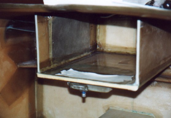
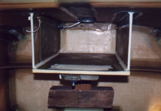
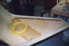
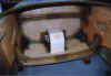
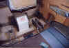
| The header tank before the rear wall is installed. |
 |
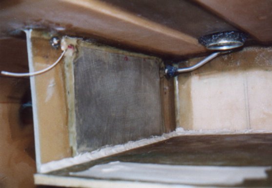
| The aluminum plate on the left inside of the cell is a
failed attempt at making the capacitive fuel sensor. Also seen is the vent tube. To try to
get the most from the tank I installed a tube that reaches to the very top of the tank
next to the fill cap. |
 |
| The sump of the tank can be seen on the lower surface of the
tank. |
 |
| Dad sanding the exterior seams of the fuselage. A additional
layer of fiberglass was applied to the exterior seams to prevent the paint from cracking
in the future. Hopefully to the distant future. |
 |
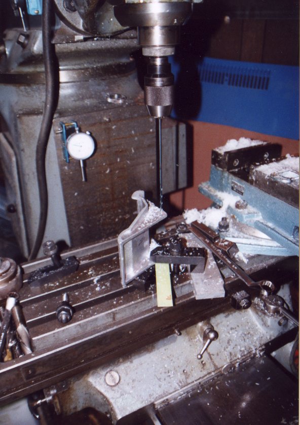
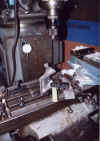
| Not required, but I used a vertical mill to drill the pivot
points of the rudder pedals. The mill made it easy with a long drill bit to get the
alignment right. |
 |
| Rudder pedal mounting points installed. |
 |
| Rudder pedal control arms installed. |
 |
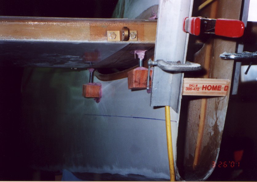
| The stabilizer is jigged in place, thanks to the mini jacks
that are bonded to the sides of the fuselage. (Mar. 01) |
 |
| Laminating between the inside walls of the fuselage and the
stab was not easy, however the next steps will be even harder. |
 |
| Seatbelt shoulder harness mounts are installed. This was
changed slightly. Instead of the mount inline with the longitudinal axis of the fuselage
they where angled toward the center of each of the seats. This will remove bending loads
if they are pulled against it in an accident. |
 |
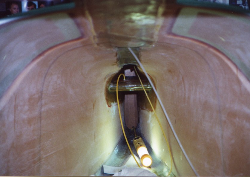
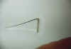
| Ant. wire routing around the elevators. Extra care was
taken
to make sure the wire didn't interfere with the flight controls. |
 |
| Pilot rudder pedals are completed. |
 |
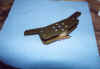
| Rudder bell-crank assembly completed. Cables run from the
pedals to this bell-crank mount in the aft fuselage, from there a push rod actuates the
rudder. |
 |
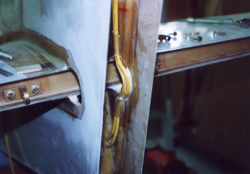
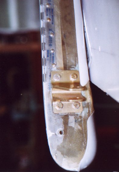
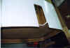
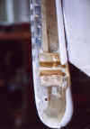
| Hinge and rudder bell-crank are installed. View
of lower part of rudder shear web showing actuator bracket, rudder hinge
and electrical conduit installation. |
 |
| |
|