| A temporary hinge is attached to the leading edge between the upper and lower wing panels. The allows the wing to be opened and closed, many many times, and still maintain the correct alignment. | 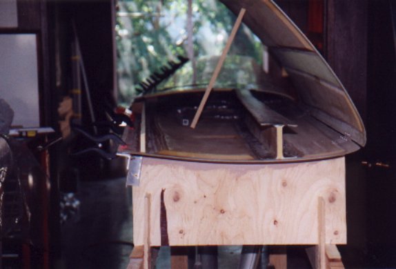 |
| During the installation of the rear spar the trailing edge of the lower wing panel was held true by clamping an aluminum angle along it's length. |  |
| Wing is installed into the jig. The rear spar has been completed at this point. |  |
| Seat pan holes cut into the upper wing skin. The seat pans are temporarily resting in place to check the fit. |  |
| The seat pan hole has been cut in the upper wing skin. Through the cutout rib "B" can be seen. Foam ribs are sanded to the contour of the upper and lower wing panel surfaces. | 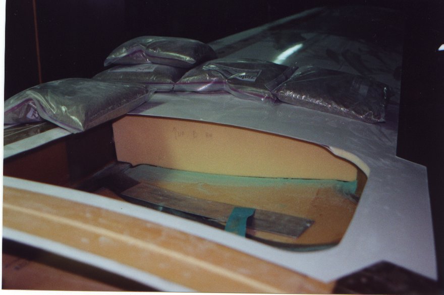 |
| The leading edge of the upper wing skin is hinged to the lower panel to allow the repeated checks of the ribs fit. |  |
| The first rib is fitted! Rib "A" in the center of the wing is installed into the wing. The darker color foam where one of the clamps is located is made of a higher density material. This is for the attachment of aircraft systems to a later time. |  |
| Aft ribs installed. Hinging the top skin is a big time saver, as the skin is positioned many times checking the fit of the ribs. | 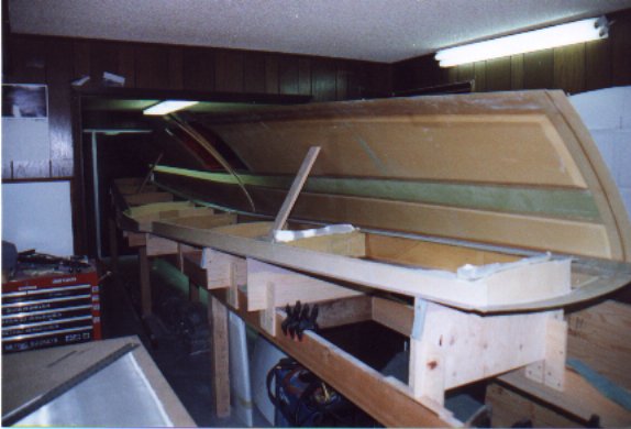 |
| The ribs forward of the main spar are formed like those aft. The bite shape cutouts in the ribs are to allow the transfer of fuel. The main fuel tank is the area between the main spar and the leading edge for the full span of the wing. It took much more time to shape the forward ribs as the hinged panel didn't work as well for the forward ribs. | 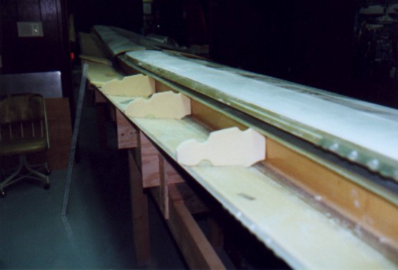 |
| All ribs are now installed. Fiberglas laminates will be applied to each side of the foam ribs as the ribs at this point have little strength. | 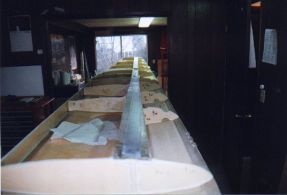 |
| The linkage tube between the control sticks requires that a threaded insert be riveted to the end of the tube. To get the five rivets at the correct distance from the end, and equally space around the tube I made a paper pattern on CAD and wrapped it onto the tube as a drill guide. | 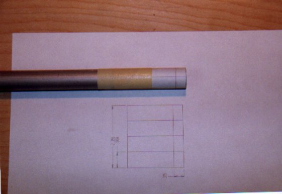 |
| Installing the forward attachment points. Aluminum angle and level are used to find the correct alignment before drilling the fittings in place. | 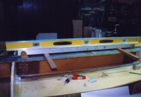 |
| Trap doors at the inboard most left and right nose ribs allow fuel to flow easily one way, towards the engine. Also seen is the forward attachment point between the wing and the fuselage. | 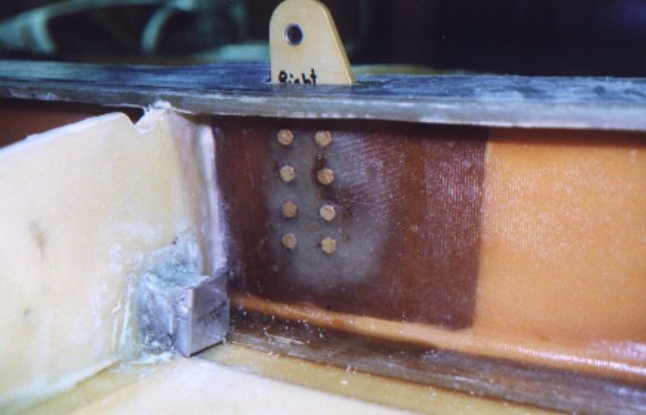 |
| A look at the open end of the capacitance fuel probe. As the level of fuel changes, the ratio of air and fuel between the inner and outer plate of the capacitor also will change. Fuel and air having different dielectric characteristics results in a change the in capacitance, this is displayed as fuel level in the cockpit. | 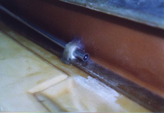 |
| Photo of the full length of the fuel probe. The probe is within the right wing, and reaches from the centerline to the last rib at the tip, 11 feet. | 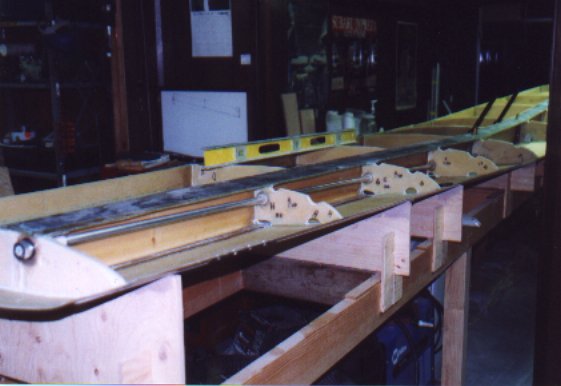 |
| Bushings are installed at the penetration of each of the ribs. This will hold the probe in place but still allow the probe to be removed if needed after the wing is closed. | 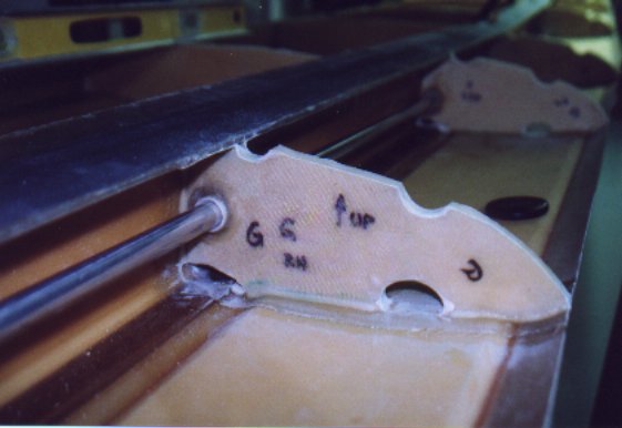 |
| Cutout in rib D complete for the aileron bell crank assembly. The different color round shape of the lower wing skin is the access hole for this mechanism. | 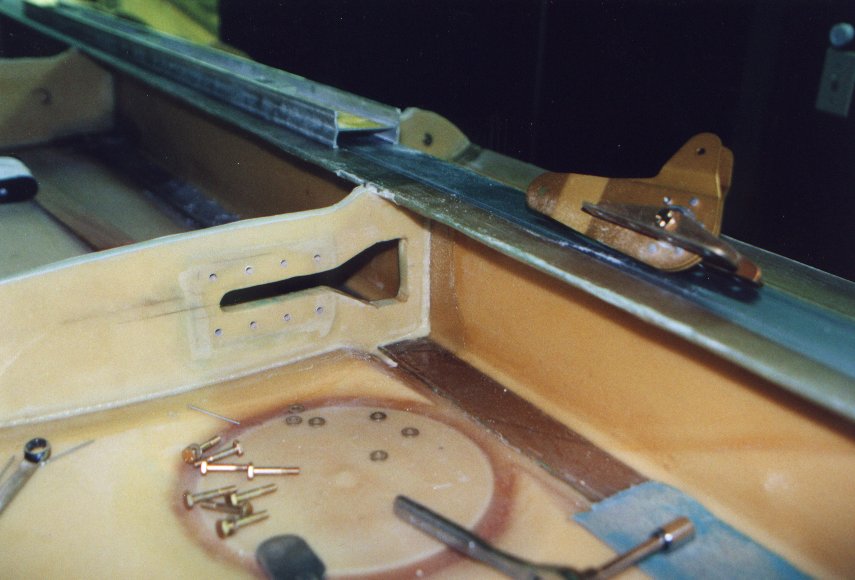 |
| Rib D with aileron bell crank installed. | 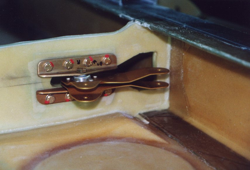 |
| The nuts for the bell crack are riveted to a plate that is in turn attached to the rib. There is no access to the back side of this rib. | 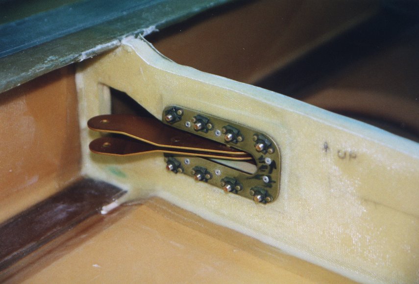 |
| The control sticks installed. The green colored rods make up the aileron control system. The black tube in the foreground is the torque tube for the flaps. |  |
| This was a big step. The hole for the landing gear is cut in the lower skin. Additional the C rib has a fiberglass cap built on top of it, and the landing gear box has been bonded into place. | 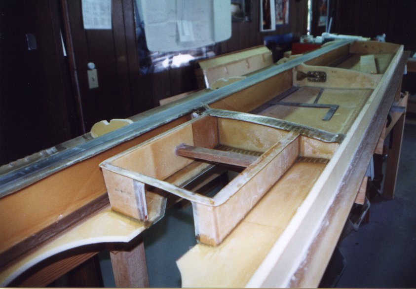 |
| Landing gear door flange being made. The piece that was cutout out of the lower wing skin was used to maintain the correct contour of the flange. Duct tape was applied to the support as a release as well as to maintain the correct height. | 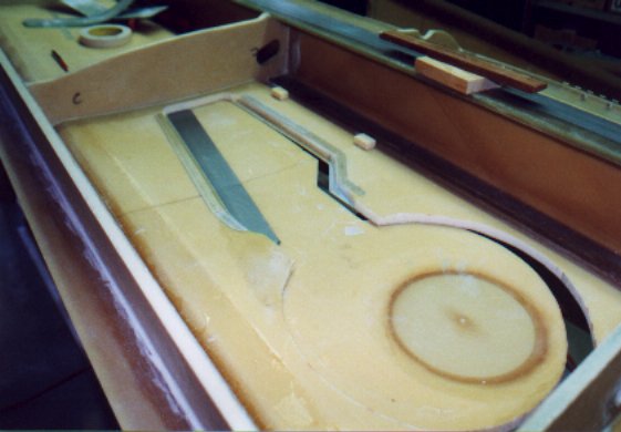 |
| Main landing gear construction started. The door is made from the cutout that was made in the lower skin for the gear opening. | 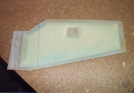 |
| Wiring conduit installed. This runs from wind tip to wing tip, and will have the wiring for the nav. lights, strobes as well as the heater for the pitot and autopilot. | 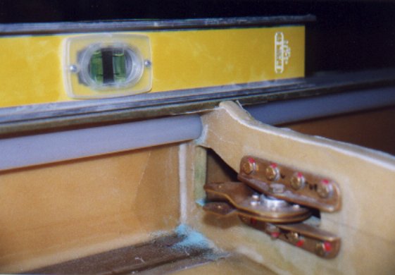 |
| Here is the start of the landing gear installation. This has been a very time consuming step. Each of the three points that the gear attaches to the wing at can be adjusted in three axis. Each axis having a different effect on the position and alignment of the gear. |  |
| After hours and hours of adjustments it is finial in. Everything seams to be correct. When the gear is down the tire is pointed straight ahead and the strut in straight up and down. During the cycling of the gear it fits though the hole in the wing, this is a good thing. And when the gear is fully retracted, the complete assembly fits below the upper wing panel surface, also a good thing. | 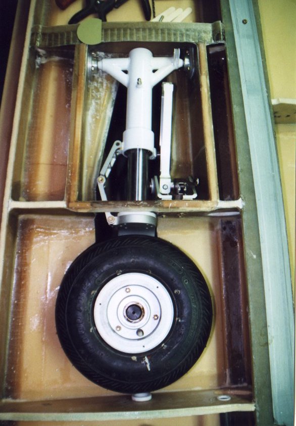 |
| Looking from below at the left gear. I am not going to install the gear door at this time, as the manual instructs. I am going to build a jig to flip the wing over later, and at that time will install the main gear doors. | 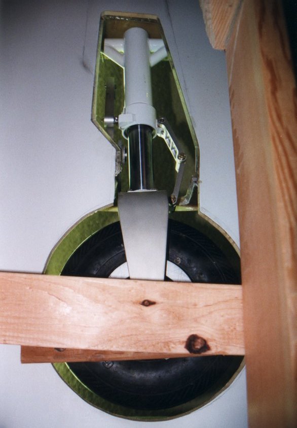 |
| Starting the mockup and adjustment of the right gear. Lots of c-clamps and of every size and shape are used. | 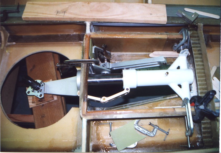 |
| Routing of the hydraulic lines within the landing gear box | 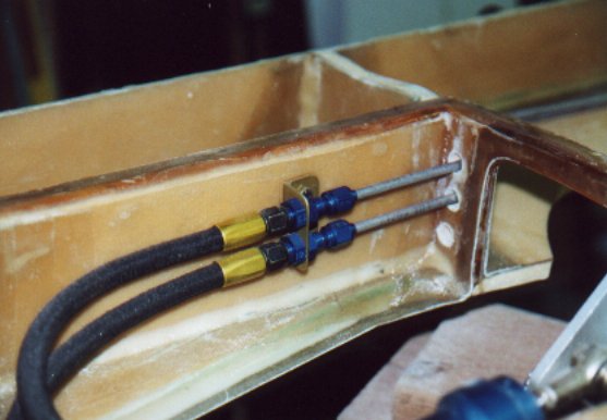 |
| I changed the way the hydraulic lines are routed. Instead of aft of the rear spar,
between the spar and flaps, I moved them forward of the spar. I doing so I believe the
installation is cleaner, easier, and has less joints. Less joints means less leaks. |
 |
| This is where the line pass though the rear spar, at the mid point of the spar within the copilot seating area. | 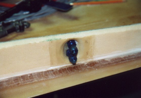 |
| Overall of the S-Tec roll servo installation. The servo can fit though the aileron bell-crank inspection hole after some slight disassemble. | 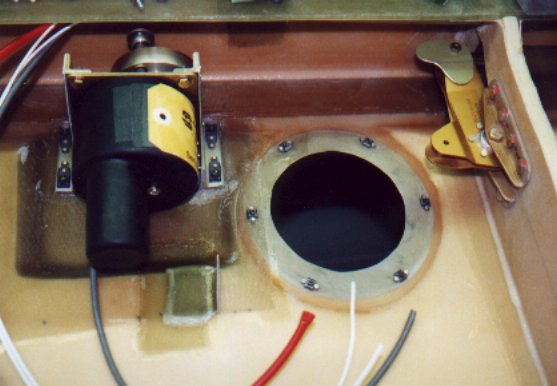 |
| On the left aileron bell-crank an addition tab was riveted to allow the servo to connect to the control system. | 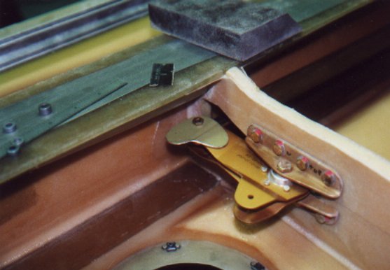 |
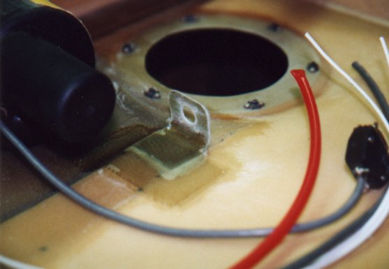
| For the connector of the servo a fiberglass bracket was made. This was done by
building laminates within an aluminum angle. The angle is used as the mold. Much lighter
and very easy. Note red pitot line. The end of the line was heated and then sealed to prevent FOD. |
 |
| Roll servo side brackets | 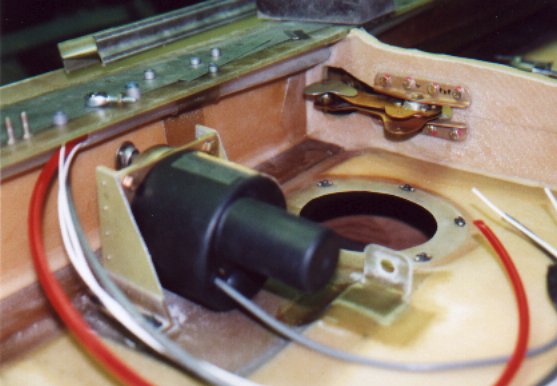 |
| Roll servo installed | 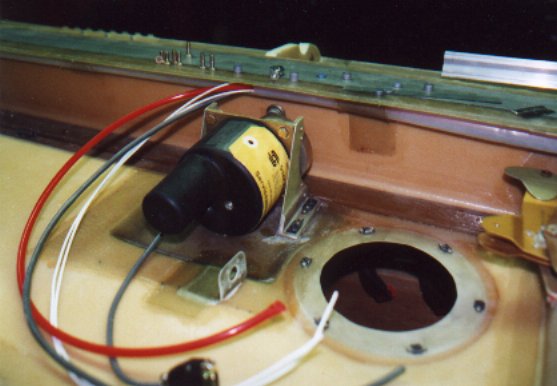 |
| The flap attachment points have been started. |  |
| A straight piece of aluminum angle is used to insure that the three flap pivots are in alignment. |  |
| Inboard right jigged and ready to be drilled in place. | 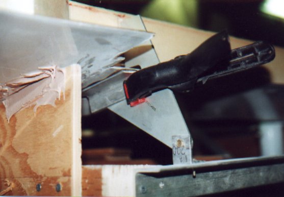 |
| AOA ports installed in the right wing. The pressure at the upper skin surface, the lower skin surface and the pitot and static ports allows a onboard computer determine the angle of attack. | 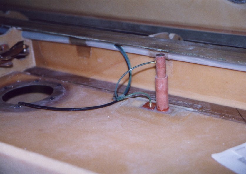 |
| Right fuel vent float valve (FVFV). As the fuel probe was placed where the FVFV assembly was to be placed, the FVFV was moved forward requiring some shaping of the housing. The fuel probe was place under the main spare cap to prevent damage while fueling. | 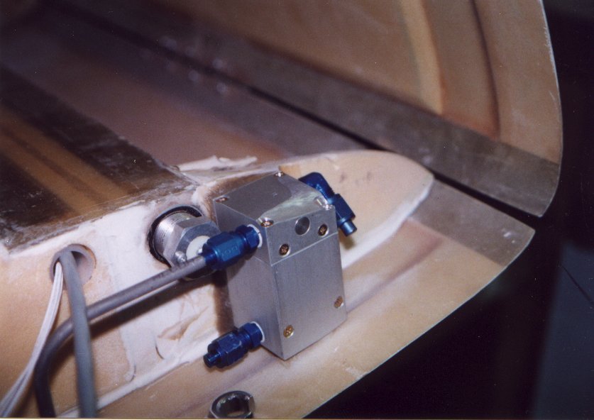 |
| Left fuel vent. Located in the normal position, close to the main spare. | 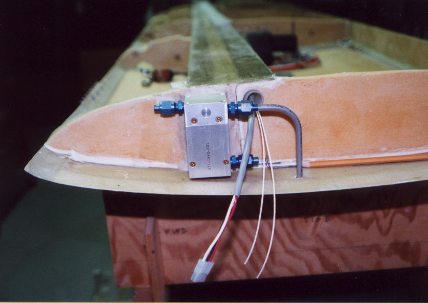 |
| Nut plate installation for flap hinge plate. | 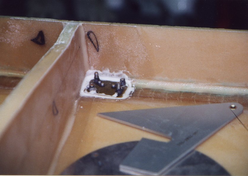 |
| Finished flap hinge plate. |  |
| IT IS TIME TO CLOSE THE WING. I thought this would never happen! On a Saturday morning the team arrived. Dad, and my two brothers, Andrew and Peter, as well as myself made up the team. After one last, finial, for sure, are you really sure, check, the process of closing the wing started. |
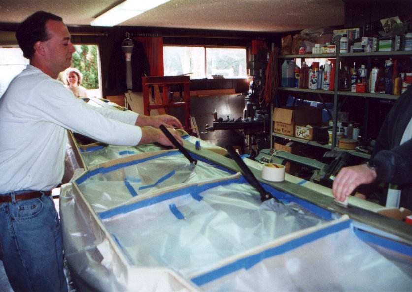 |
| The top of all the required ribs where V cut. Wax paper tapped into each bay to catch the drippings. The fuel bays were cleaned. Then the resin was mixed and the closing started. | 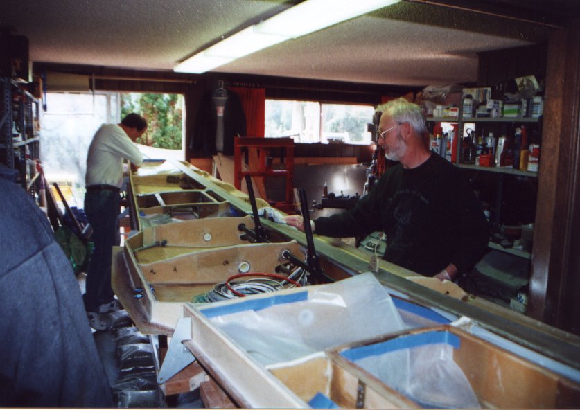 |
| We used everything we had as a weight on top of the wing. About 35 ten pound bags of sand, 35 bricks, 20 pounds of lead, a bag of grass seed, a bag of bird seed, a bag of fertilizer, and anything else that had weight to it. | 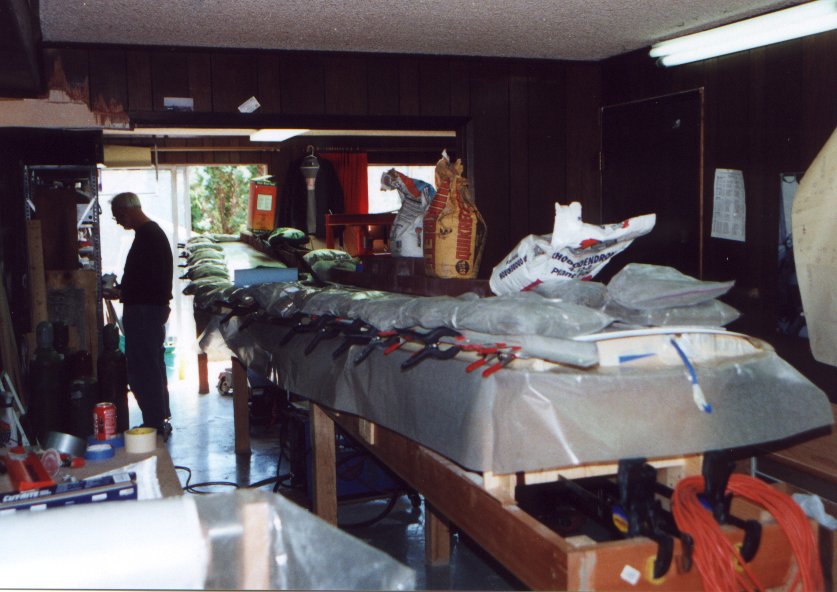 |
| Aft shear web tie completes the rear shear web. | 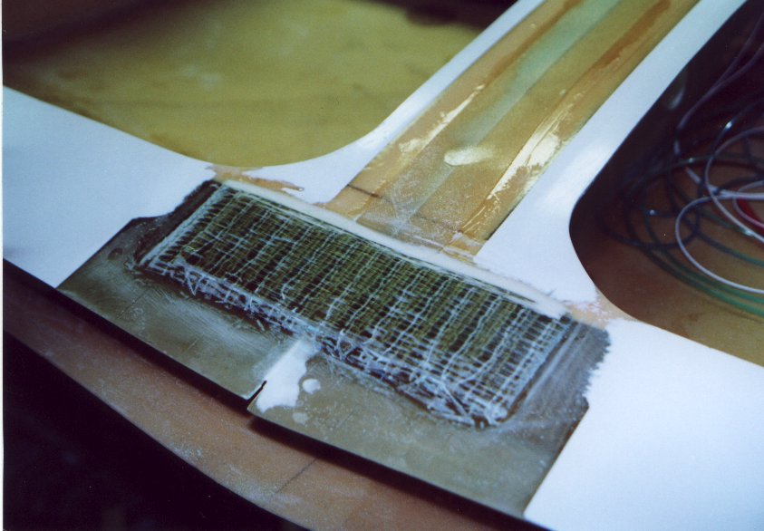 |
| Peter safety wiring the cover plate above the fuel sump. |  |
| Forward wing attach brackets. |  |
| Inside look at the short tips. |  |
| Short tip before the Nav. and strobe lights. |  |
| The extended tip had a problem. When the tip where made they came from a mold that was taken from the Glasair I wing. This wing had a cusp on the lower aft surface. To remove this cusp and have it match the ailerons slits where cut into the inside surface and the form core. Then the tip was clamped on a flat surface and two layers of laminate was applied to restore the inside surface. These removed the majority of the curve. |  |
| The jigging of the extended tips. |  |
| New fuel fittings. The part on the left is the standard fitting. I didn't like the fitting as the hose is attached via a slip on fit and hose clamp. So I made a new fitting. On the right. This will allow an AN hose to be installed between the tip tank and the fuel vent float value |  |
| Fuel fittings installed on the partial inboard rib of the extended wing tip. | 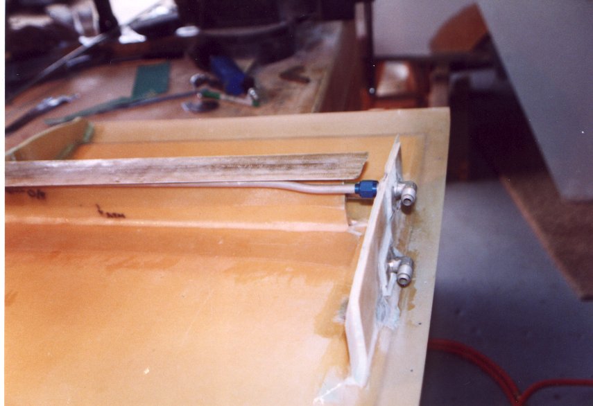 |
| The closeout for the navigation light and strobe is seen here. The tube is the conduit for the wires. | 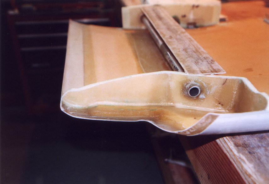 |
| The aileron hinge was riveted to the lower wing surface. |  |
| Just before closing the aileron. Not much to them. A light weight spar an a rib at each end. |  |
| Outboard aileron rib and the metal backing for the hinge. |  |
| I closed the aileron on a flat work table. |  |
| Aileron installed on the wing. | 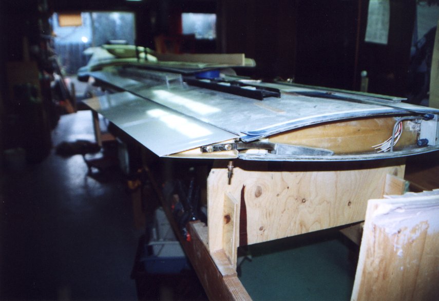 |
| Electrical actuator for the flaps is installed. Great fun to hook it up to power and watch it run back and forth. | 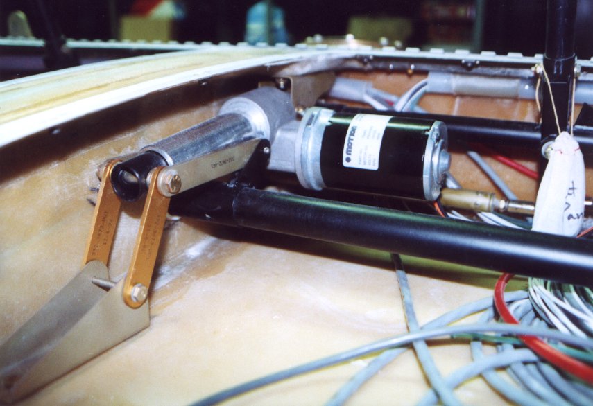 |
 |
|
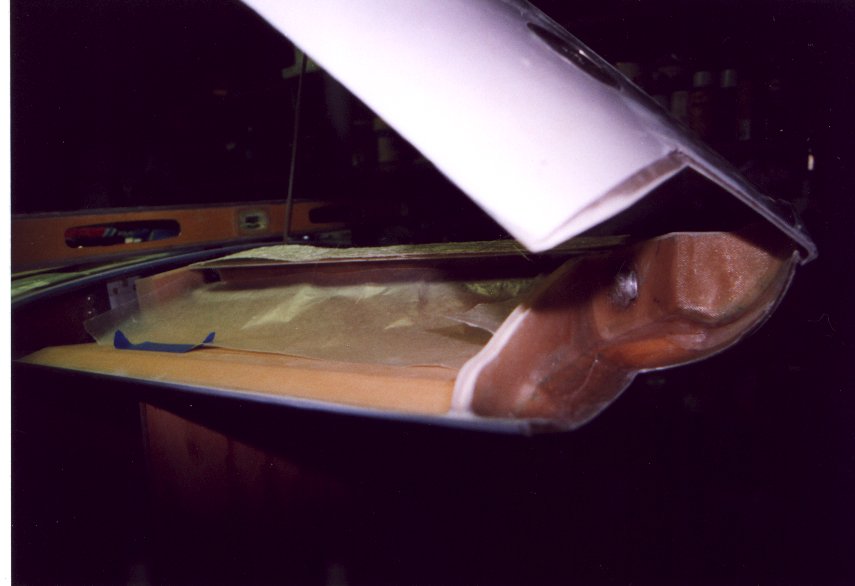
| The spar cap is treated the same as the spar in the rest of the wing, an addition layer of roving weave cloth is laid on top before closing. | 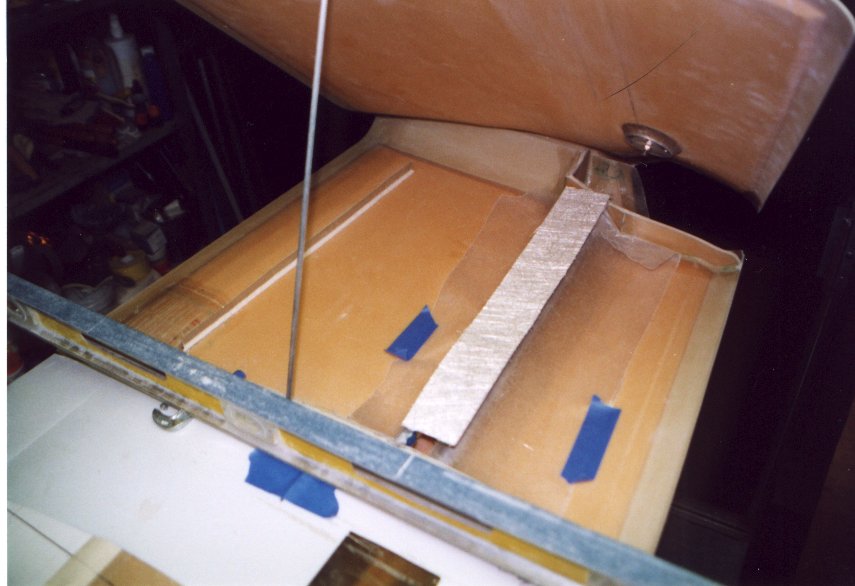 |
| Last check before closing the tip. | 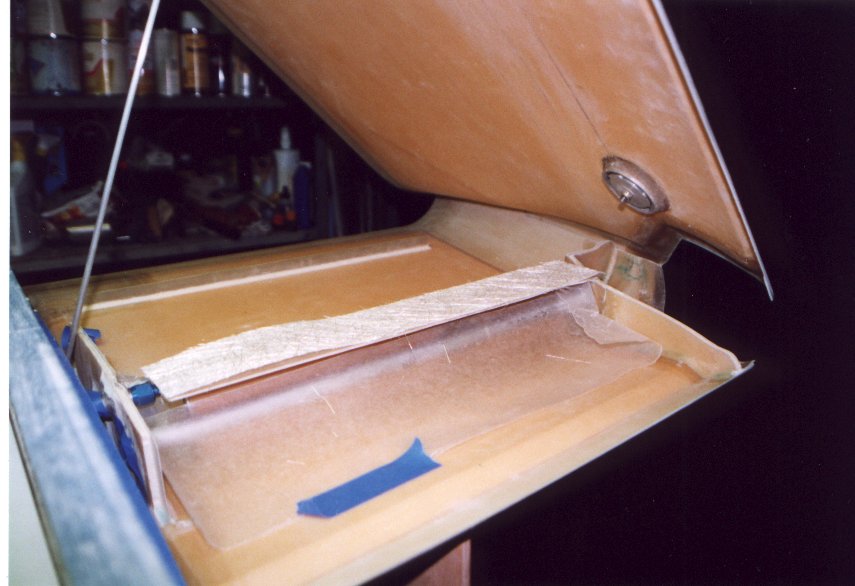 |
| The extended tip was closed in place attached to the wing. | 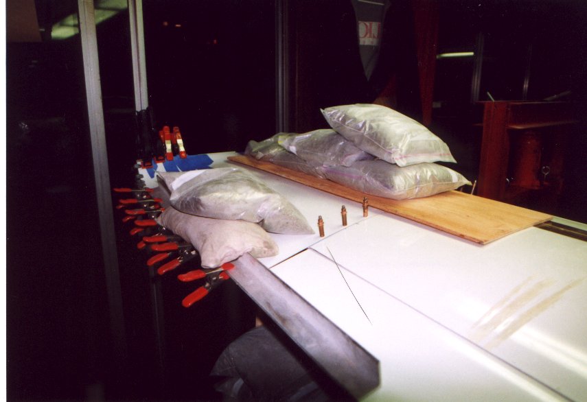 |
| A straight piece of aluminum angle is position and held in space by any means available. It Doesn't need to be pretty, as nobody will every see it and the aileron will soon be closed. This magical spot in space is found from referencing the wing tip. As the aileron will align with the trailing edge of the tip and this was set very carefully using the ordinates of the airfoil. As for the trailing edge of the inboard end it will can also be found the same way. |  |
| Control rod in installed and connected to the aileron. |  |
| Just before closing the flap | 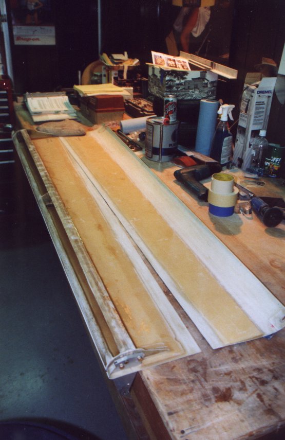 |
| The jig for the aileron in the same as the aileron. | 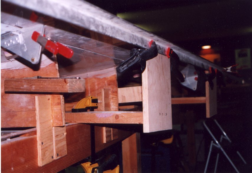 |
| Inboard flap hinge installed. The hinges of the flap where install with the flap jigged in place with the wing. |  |
| Completed aileron on wing. The counter weight can been seen at the end on the wing. | |
| Wing with extended tip and aileron | 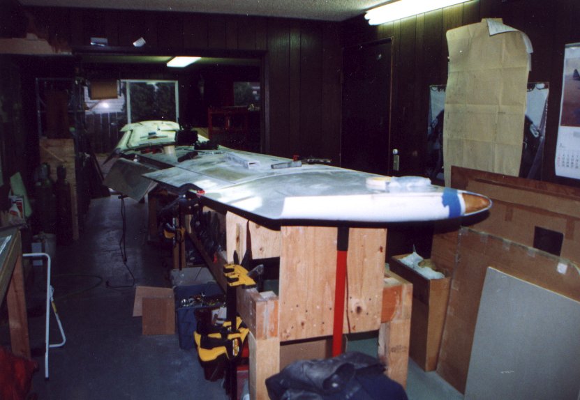 |
| Flap motor movie Warning 1 meg. Sorry only works with I.E. | 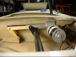 |