


Stabilizer and Elevator Construction
Last updated on 01/12/04
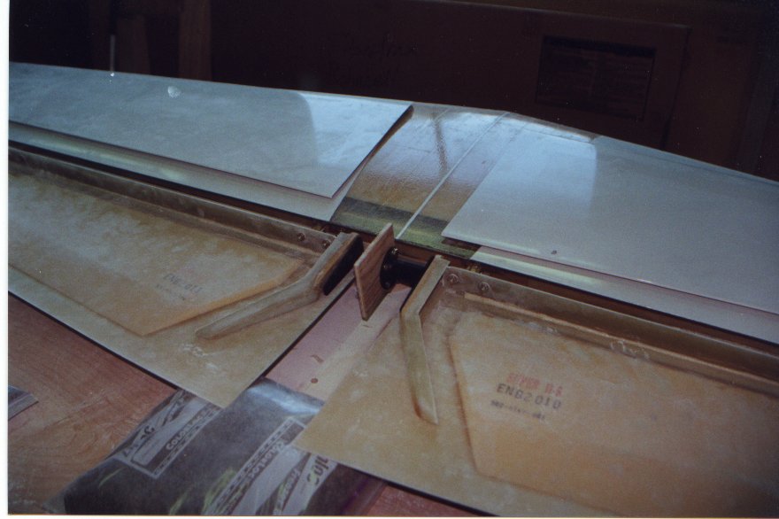
| During the installation of the rear spar to the stabilizer skin, a straight edge was held up against the rear spar to help with the alignment and small form blocks were hot glued in place to hold the alignment. All the ribs for the stabilizer are pre-made except for the outboard ribs. | |
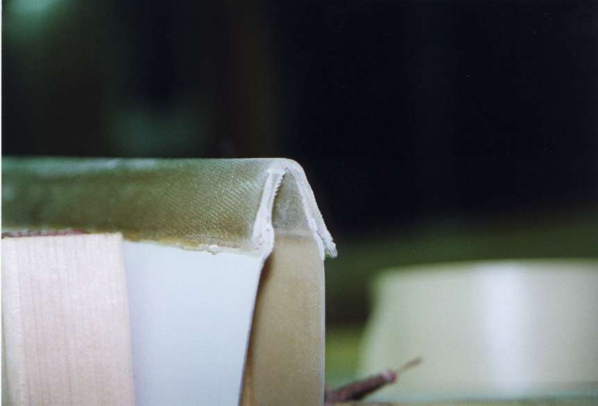
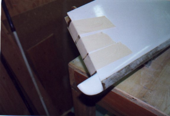
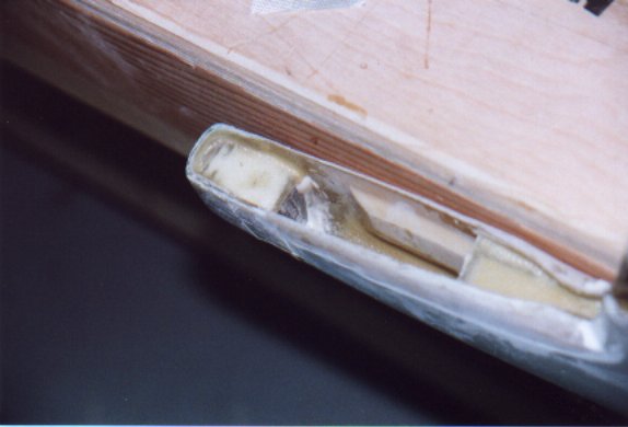
| Close-up of an outboard rib. The rib is cut from a sheet of foam, sanded to the correct shape, sealed and then bonded in place. The next step the photo doesn't show is a multi layer laminate of fiberglass on each side and lapping onto the skin. | |
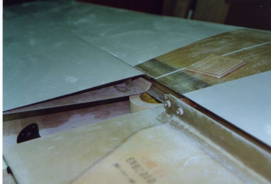
| Nutplates were installed to allow the hinge brackets to be bolted on. The nutplates for the hinge brackets were riveted and fiber glassed into place. | |
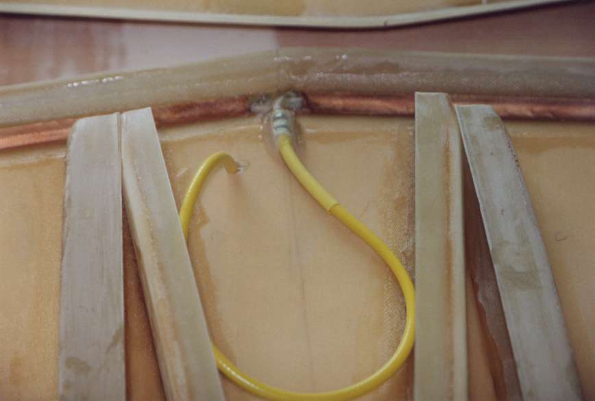
| Before closing of the two stabilizer skin panels I installed a fold dipolar VOR nav. antenna in the leading edge. An advantage of composite construction is that the antennas can be mounted internally, eliminating the drag that they normally produce. | |
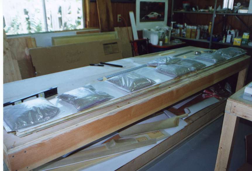
| Stab closed. Sand bags are used to apply the clamping force during the cure of the bonding. | |
| After the two panels of the stab are bonded together the leading edge laminates and rear spar laminates are applied. | |
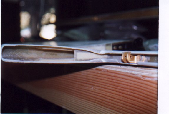
| Elevator spar laminated in place and this height has been trimmed so that the lower panel fits to the surface of the stab. (in this photo the upper surface is really the lower surface) | |
| Elevator inboard rib install along with the elevator torque tubes. | |
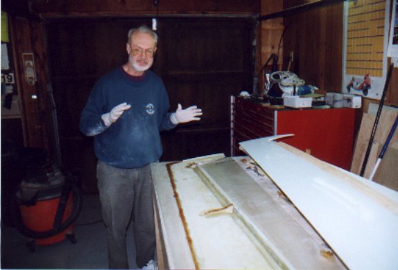
| Dad at the ready. Closing an elevator | |
| Stab and both elevators all bolted together for the first time. | |
| The ends of the stab are sealed as well as caps are put on the ends to blend with the counter weight arms of the elevators. | |
| A look into the counter weight arm of an elevator. The lead counter weight has not been add yet. | |
| Lead weight installed into the tip of the counter weight arm. | |
If you have entered this page from outside the main home page please go here