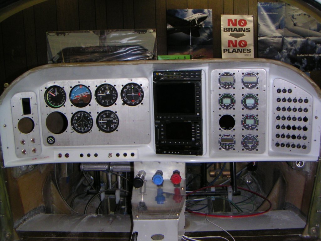
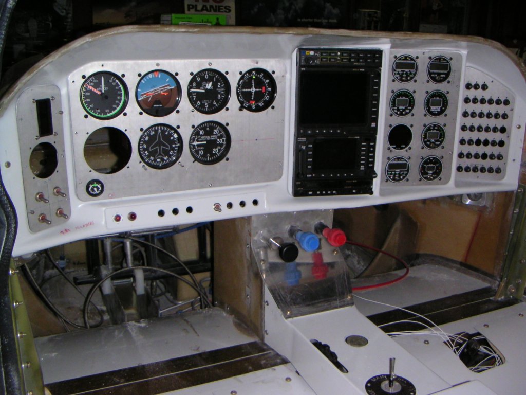
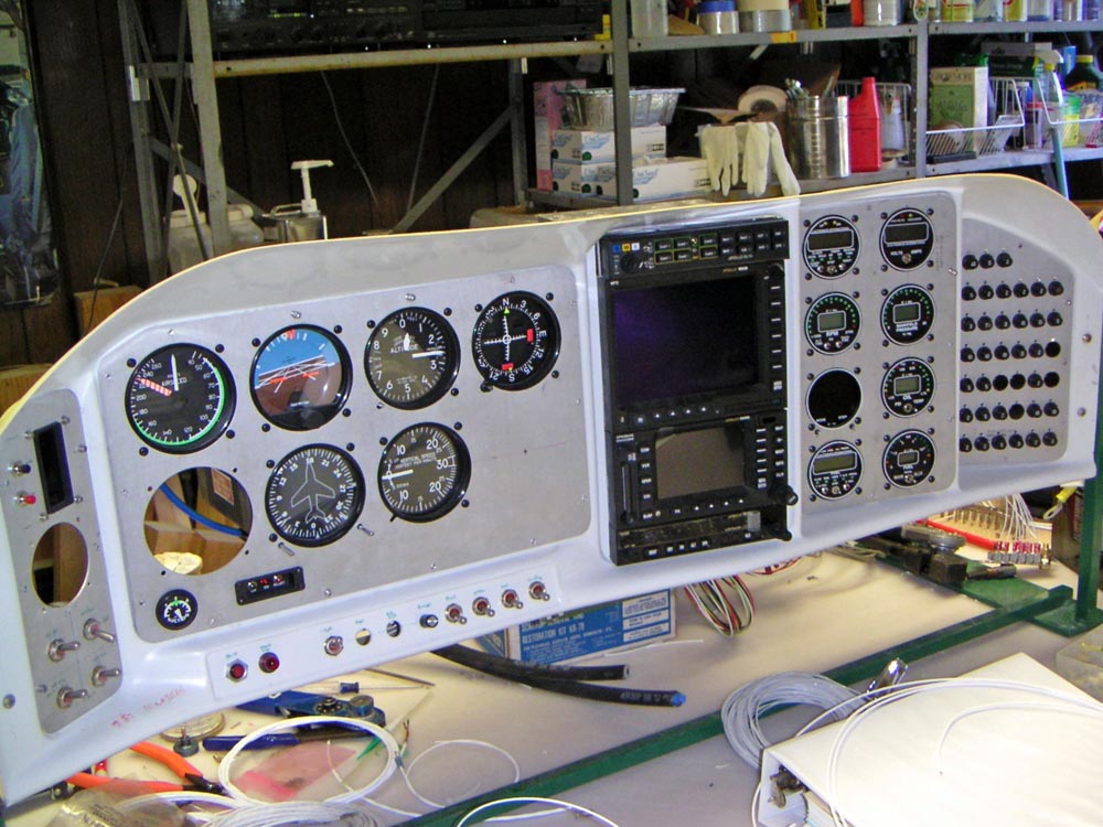
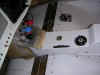
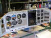
| Mockup of the panel. I started out designing a VFR panel
but by the time I was finished it was full IFR. The autopilot is missing
and fits in place on the T/C. |
 |
| The engraving still needs to be finalized. |
 |
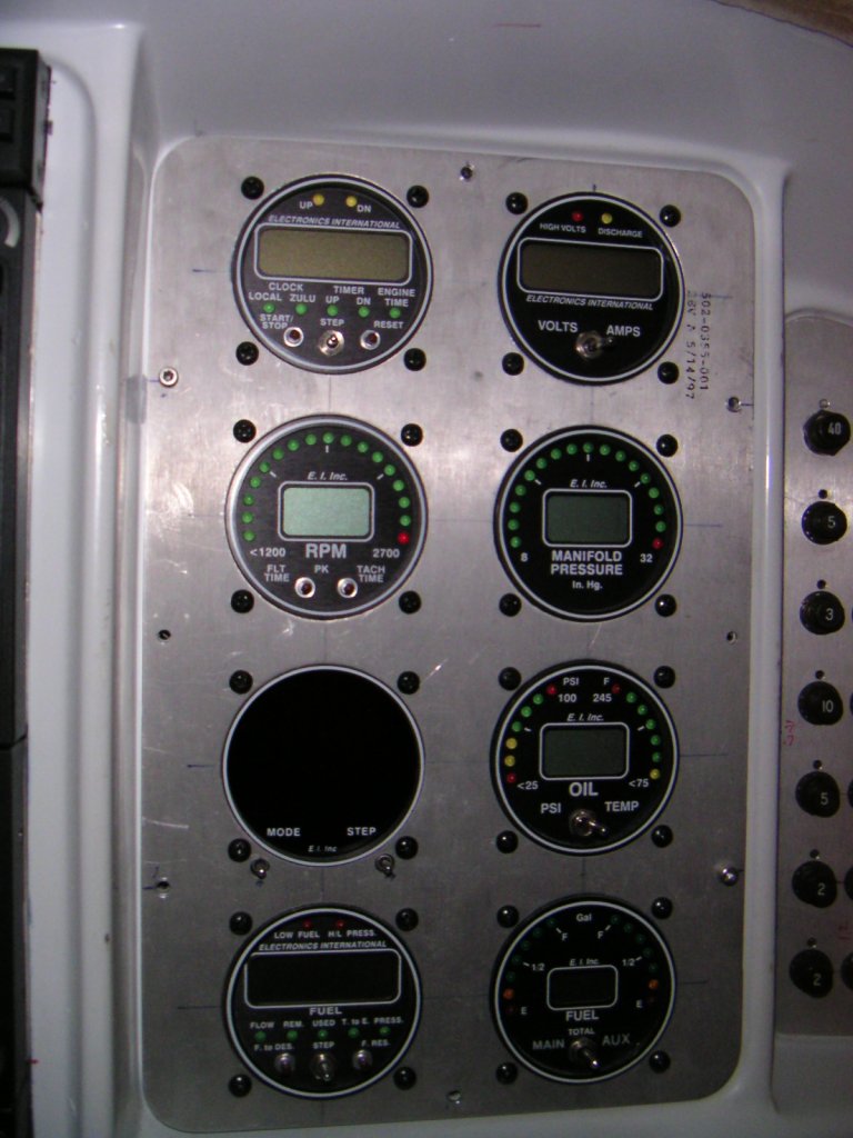
| I think I will move the clock from the engine instrument
panel to the far left panel. More convenient to reach. |
 |
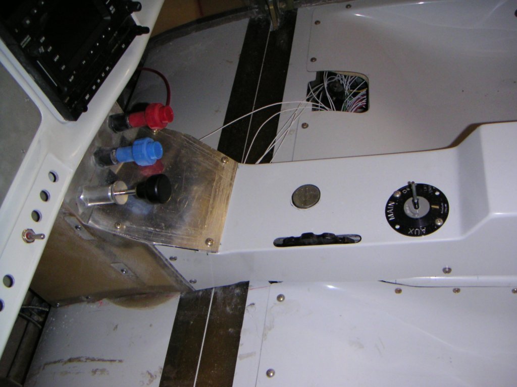
| Center panel will have a hydraulic pressure gauge as well
as the gear and flap switches. I am also going to put the gear indicators
in this location. |
 |
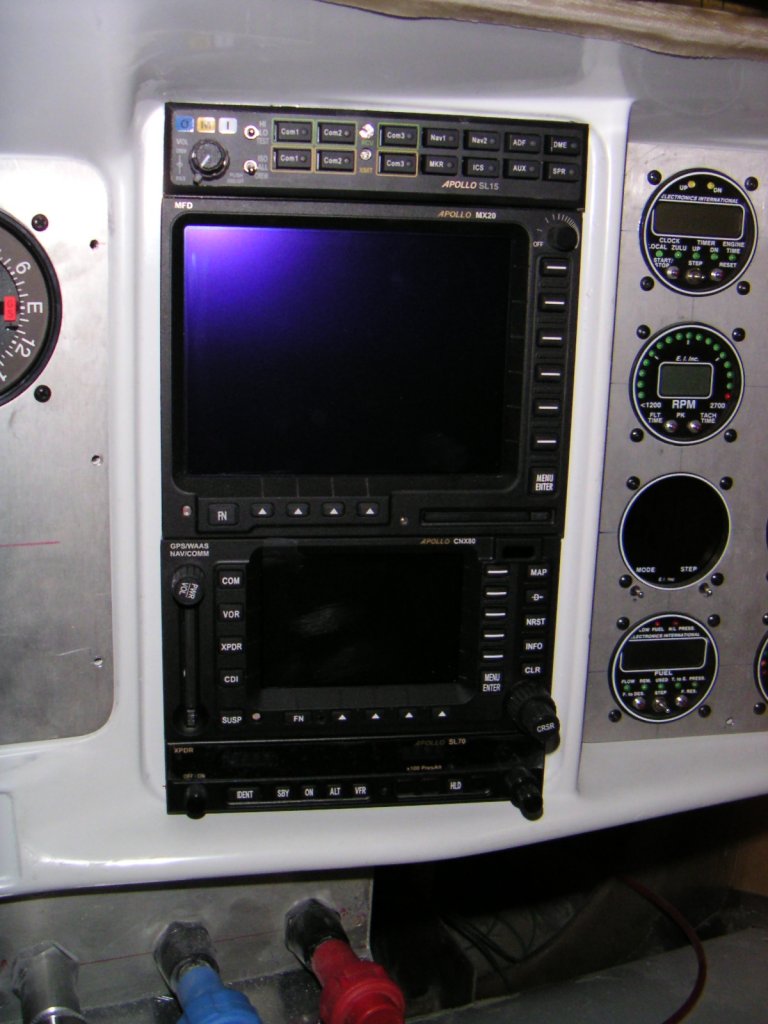
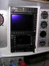
| Can't wait to power up the avionics and try them out. From
top to bottom Audio Panel, Moving map, WASS GPS / NAV / COMM,
Transponder |
 |
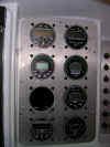
| I like the idea of individual engine gauge. |
 |
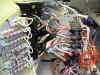
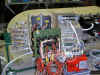
| A mess of wires!
Engine instruments wiring. |
 |
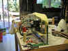
| Wiring of the avionics |
 |
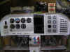
| The mechanical fitting
of the panel is almost complete. |
 |
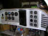
| Side view of panel |
 |
| |
|
| |
|